
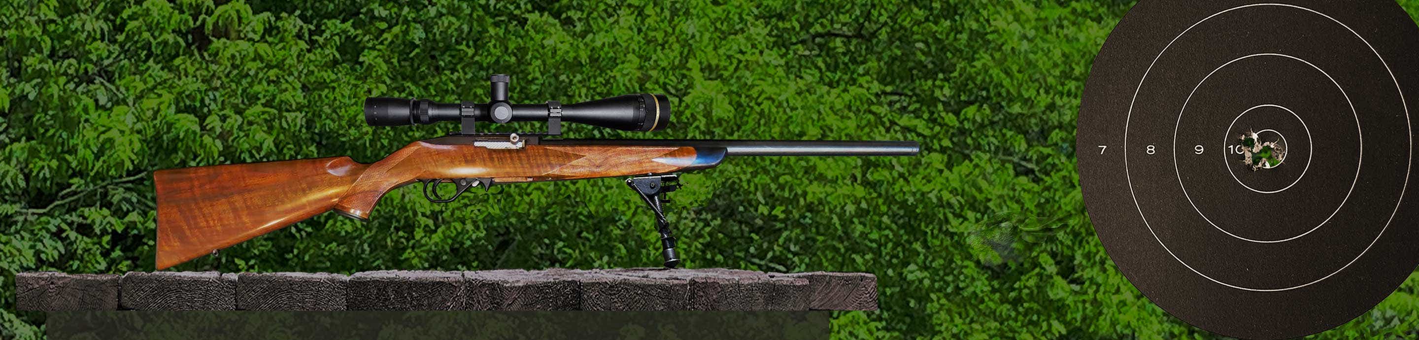
Hello, I have a possible solution for those wanting to mount a red dot to your p22. It is a 3d printed design using a carbon fiber infused nylon that is temperature resistant to 318c , extremely impact resistant and chemical resistant. This is still being tested and experimented on but I have 500 rounds through the most recent revision. All casings ejected correctly except one instance where the last rounds casing stayed inside but immediately dropped out after releasing the mag for the next full mag. The mount is bolted to the frame using custom machined double threaded barrel nuts that are intended to replace the 3x24mm and 3x22mm coil pins, allowing you to remove the mount and keep the mounting nuts installed. The actual hole diameters on my P22 frame measure 3.098mm (.122) so that's what the current pins are machined to. the tolerance for the P22 frame holes is 3mm +.15mm/ -0.0mm (.118 +.005/-.000). My frame runs at the high end, other frames may not. I'm seeking individuals interested in sharing their frames diameters and potentially testing a red dot mount and hardware themselves. Thank you.
![Image]()
![Image]()
-
Whether you're a greenhorn or a seasoned veteran, your collection's next piece is at Bass Pro Shops. Shop Now.
Alexirv600

- Status
- Not open for further replies.
Walther P22 red dot mount
Alexirv600
Discussion starter
10 posts
·
Joined 2021
- Add to quote Only show this user
Hello, I have a possible solution for those wanting to mount a red dot to your p22. It is a 3d printed design using a carbon fiber infused nylon that is temperature resistant to 318c , extremely impact resistant and chemical resistant. This is still being tested and experimented on but I have 500 rounds through the most recent revision. All casings ejected correctly except one instance where the last rounds casing stayed inside but immediately dropped out after releasing the mag for the next full mag. The mount is bolted to the frame using custom machined double threaded barrel nuts that are intended to replace the 3x24mm and 3x22mm coil pins, allowing you to remove the mount and keep the mounting nuts installed. The actual hole diameters on my P22 frame measure 3.098mm (.122) so that's what the current pins are machined to. the tolerance for the P22 frame holes is 3mm +.15mm/ -0.0mm (.118 +.005/-.000). My frame runs at the high end, other frames may not. I'm seeking individuals interested in sharing their frames diameters and potentially testing a red dot mount and hardware themselves. Thank you.
![Image]()
![Image]()
1,297 posts
·
Joined 2018
Looks like a nice design.
You may want to post this on the Walther forum.
The issue with mounting a dot on a P22 does come up there, from time to time.
P22 section -

EDIT: I see you did already post there in an existing thread. You may want to start a new thread that would make it easier to find for anyone interested.
You may want to post this on the Walther forum.
The issue with mounting a dot on a P22 does come up there, from time to time.
P22 section -
EDIT: I see you did already post there in an existing thread. You may want to start a new thread that would make it easier to find for anyone interested.
Alexirv600
Discussion starter
10 posts
·
Joined 2021
Thank you for the suggestions, I will do that.
8,912 posts
·
Joined 2005
Me, me, me.....I want one. Let's look into it first though. Pic of mine below. It's been on for years, works fine. Difficult to install. Uses steel breech block under the slide for attachment. Requires precise drilling and tapping. Your concept looks really good. I ran into two problems with my red dots. First they have to be removed to install a new battery, then of course re-zeroed. Second, with a suppressor, blow back gasses and hot debris hits it red dot lens. Without a suppressor...to a lessor degree. The final shape of my mount is to deflect even suppressor blowback away from the lens. Some of the light weight dots use high quality plastic....not high quality enough though when it comes to white hot powder. Glass is better but it is better yet to protect the lens from blowback dirt. I am experiencing no failures to eject from the longer nose mount. There are a number of threads on this way back there somewhere. 1917
![Image]()

Alexirv600
Discussion starter
10 posts
·
Joined 2021
Hey 1917, thank you for your interest. A couple years back I did something similar but only went as deep as the top of the slide. I should have tried going into the block like you did. My biggest issue was I couldn't get it to cycle more than a few rounds with either of the red dots I had. I believe they were in the 5oz to 8oz range. The last version of the mount I printed had several casings end up pinched underneath the red dot bridge and rear of the slide on its way into battery but more importantly I am having a ton of failure to fire and light strikes. I have a new hammer assembly on the way and an updated version of the mount pushing the red dot bridge back towards the rear of the slide by 2mm. As far as gasses and debris on the lens, I've only seen light smudging from expelled oil and only noticeable when looking at the glass from the front. Do you have recoil pins on your plate or are you just using the bolts for the red dot?
8,912 posts
·
Joined 2005
I bought Shield sights... 0.5 oz. so really light. Three things I don't like about them. The plastic lens on one was immediately destroyed by blowback debris. I lengthened the nose of the mount to protect the lens on the second one but plastic (acrylic) doesn't hold up in my opinion. A glass lens which they offer adds about 0.1 oz to the weight. I don't know what a P22 will ultimately cycle but it is much higher than the weight of these dots. The next thing I don't like is that the sight has to be removed to change the battery and they don't last two or three or four years as advertised...even in dark storage. A year is the max....but that all depends on how often you have it out shooting. Of course you have to re-zero. The last thing is no adjustment for the dot brightness. It is automatic but in my opinion way too bright for target shooting. Quick acquisition for steel with the 4 moa is fine. Trying to draw a fine bead on a target...nope, the dot is too bright. So, i put a strip of duct tape or similar as a hood over mine to knock off the light. The dot then dims to where I can see a black spot on a target. My solution is hard to mount...Walther/Umarex could make all of this much easier but you can't dig into the slide as itis thin and the firing pin runs immediately below the inner top. No dovetails possible with the stock slide. I can remove the slide and disassemble the pistol for cleaning with the sight left on the slide. A plus.....perhaps. 8 oz is half a lb....you sure about that weight? PM me if you will. I'd like to go over a couple of things. 1917
8,912 posts
·
Joined 2005
Oh yeah....roll pins....nope. Machine screws.These pistols are tiny. The slide is too thin to drill and tap. I drilled through it and through the inner steel breech block and then threaded the breech block in order to attach an aluminum mounting base. I think 3mm screws from the specialty screw drawers at Lowes. I forget the size, had to grind them all to fit lengthwise. Stuff happens around the breech block, stuff happens inside the breech block....so you have to choose your mounting holes very carefully and the length of the attachment screws is critical. They can't be sticking out the bottom of the breech block. I blue locktited them in place. To mount the sight I carefully aligned it on the mounting plate and then drilled and tapped for the mounting screws that came with it. I also drilled a hole over the extractor roll pin so access is provided to it without removal of the base. Everything has worked fine, stayed tight and stayed zeroed with exception of having to change the battery a couple of times already. But, it isn't a huge effort to re-zero. Some sights allow you to change the battery without removing the part....slide out tray. 1917
8,912 posts
·
Joined 2005
You have to drill and tap for something like this. 3mm tapered flat head screws required so the heads can sit flush in a countersunk hole on the top of the mounting plate. Nothing can stick up to interfere with the base of the red dot when mounted. As I said....these pistols have tiny parts. 1917
![Image]()

8,912 posts
·
Joined 2005
I was out shooting mine last weekend....bang, bang, bang......ping, ping, ping... If you hold the dot on the steel targets that is where the round will hit. I'm 75 and have not been entirely happy with my cataract surgery nor having to go back and have the skin that grew over my new lenses lazer burned off and I think it is coming back again. So, it is a testament to how good red dots are that I can rapidly hit a 10" steel plate at 25m, offhand....with every shot. I have to look through the very bottom of my glasses to have iron sights in focus. 1917
Alexirv600
Discussion starter
10 posts
·
Joined 2021
It seems I can't do PMs until I have reached a certain number of posts.
8,912 posts
·
Joined 2005
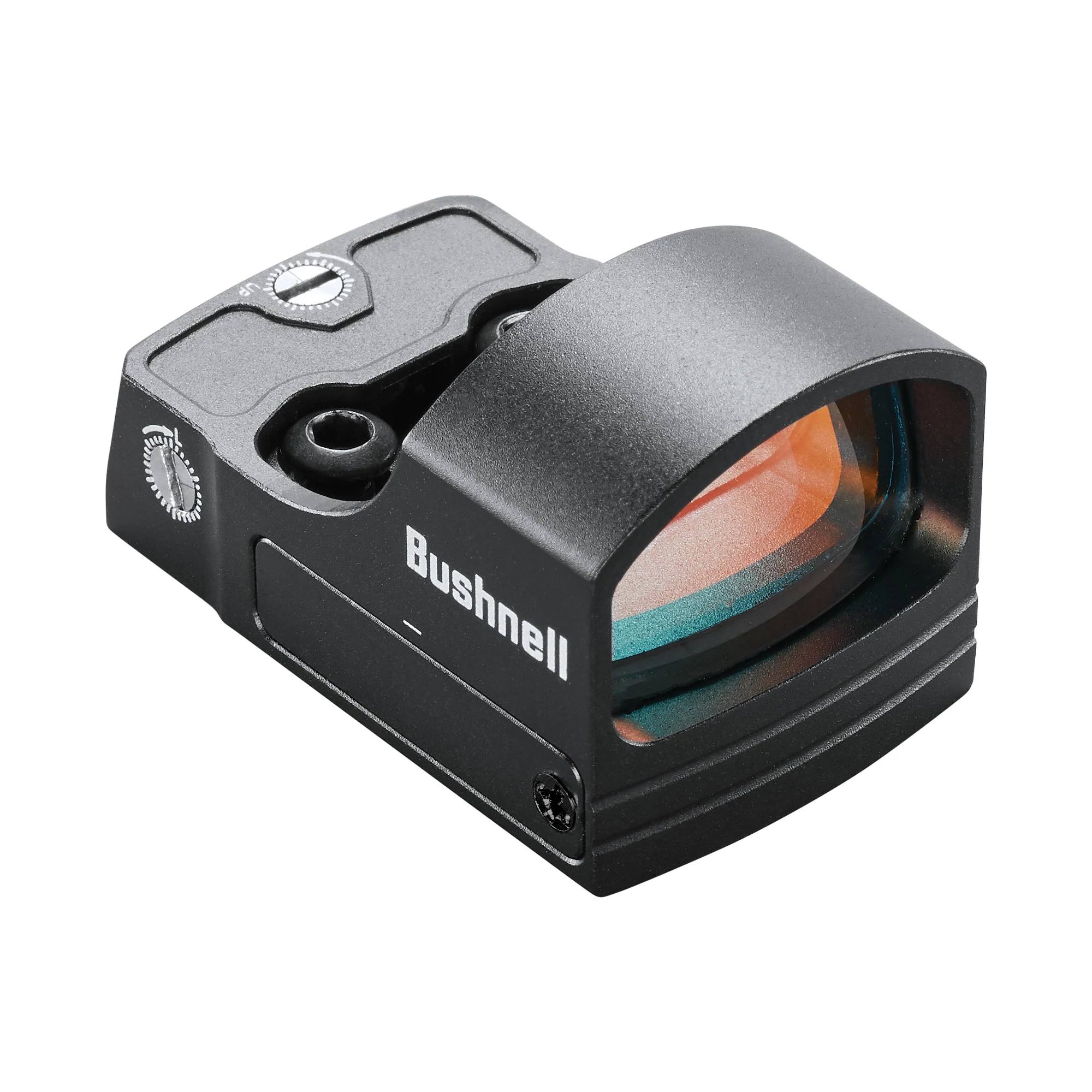
Well, get that post count up. Make short ones. Something like the one below would probably be a better choice for my pistol. Light weight, inexpensive, glass lens, adjustable brightness and the battery can be changed with a sliding tray...no more removing the dot to change the battery. I might get one if it looks like it will mount properly for my system. Your mount is on the frame, not the slide so weight would be not an issue. Mine is on the slide so the red dot cycles with the slide. I've had no issue with damage to the slide from impact of the screws through the slide and into the pinned in place breech block. If it works on a 9mm or 44 mag....it will hold up on a .22. Of course there is a limit to how much weight a .22 will cycle and the P22 already has a pretty heavy slide.
Can you make a custom mount for my system? How about a 3D slide with properly designed mounting points on the rear of the slide? I don't know anything about 3D printing or materials. 1917
 www.bushnell.com
Can you make a custom mount for my system? How about a 3D slide with properly designed mounting points on the rear of the slide? I don't know anything about 3D printing or materials. 1917
RXS 100, 4-MOA Red Dot Reflex Sight | Bushnell
The RXS-100 Reflex Sight features a precise 4-MOA dot. Upgrade your aim with this reflex sight. Shop Bushnell today.
www.bushnell.com
8,912 posts
·
Joined 2005
Alex there are forty billion P22s out there and I think a number of people would be interested in your mount especially since red dots have come down in price. Your concept is very imaginative and looks great on the pistol. I think it likely that it is patentable.....but not if you go showing it all over the world. Someone will grab your idea. I know nothing about patents and am convinced that most of this patent pending stuff is simply a warning that you are in the process of applying for a patent...when no such serious effort is really being made. A lawyer at the Walther Forum comment several times that I was putting up stuff that could be patented.. I had no interest in manufacturing gun accessories going through the patent process, etc. You might. You concept is ergonomically much better than the old Walther bridge mount.
Both require removal of the mount to remove the slide for field stripping. If that can be solved....a big plus. Walther's apparently didn't sell but it was ugly, bulky and a bit flimsy in my opinion. I had one....mailed it to someone in Arizona for free that wanted it. They haven't been made for years.
I really like your mounting concept. I know nothing about 3D printing or costs involved. Could the part be made to mount on only one side? Could it be raised a bit so that the slide could be removed without disturbing zero? Could this allow the red dot to be moved rearward to get it away from the ejection port...spent case interference and protect it from .22 blowback gasses. We can fix the stuck spent case problem. Can it be made in two parts so that the mount base slides on and off and locks in place without upsetting zero but allowing the slide to be removed. Getting the dot off the slide is a good step one. It is a .22 pistol so recoil is minimal as is cycling a heavy dot. Then of course there is a need to look into is there any standardization to red dot mounting holes, length, etc. In other words, can you make one mount that fits many compact red dot sights?
My breech block is a no go for most people. It requires very precise drilling...it does work well and the sight is on the slide so it doesn't have to be removed in order to remove the slide. I added a nose that overhangs the ejection port. I'm having no ejection issues. I forget what all of mine weighs with mounting screws, aluminum base and the dot with a battery but it is still light. Shield's cost $300 ea. The Bushnell above with all of the features I would want costs $100. It was not available a few years ago or that is what i would have purchased. Acrylic lenses are no good in my opinion where ejection debris can hit them. They soon scratch up regardless of care in cleaning. I notice Shield advertises a much harder finish on their acrylic lens now...I don't buy it. The sight also comes with glass for the same price now. Still $300, still have to be removed to change the battery, still no brightness adjustment.
They offered to put glass in my sights for $80 ea....I haven't taken them up on it yet. They are in England. The Bushnell indicates the lens is glass. I'd go glass. A hole for the serial number is a nice touch. Really good concept and perhaps removing the frame pins and reinstalling will not disturb the zero. You would need to test....or better yet me....lol. I suppose you can color the material....black, field dark earth, green, or my favorite....pink polka dot. I will be glad to help with measurements, testing, etc. My concept works fine but is above the skills of many I expect and the dot still rides on a fairly loose slide that wobbles from side to side on the frame. 1917
8,912 posts
·
Joined 2005
The P22 is a compact pistol, requires a small red dot in my opinion to look good...
Don't forget the similar Ruger SR 22 and Smith Compact...they need some red dot options as well in my opinion. Many of these new 9mm pistols are coming designed with removable plates for drop in red dots. There is no way to do that with the thin zinc alloy slide on the P22. You can do a lot of things with a steel gun that you can't with an alloy one. You can do a lot of things with a firearm designed for sight options from the git go that you can't with one that isn't. The P22 is still a plinker/trainer in my opinion and not a self defense firearm....but a red dot certainly helps with both when it comes to fast and accurate aiming. My wife calls it cheating. 1917
Don't forget the similar Ruger SR 22 and Smith Compact...they need some red dot options as well in my opinion. Many of these new 9mm pistols are coming designed with removable plates for drop in red dots. There is no way to do that with the thin zinc alloy slide on the P22. You can do a lot of things with a steel gun that you can't with an alloy one. You can do a lot of things with a firearm designed for sight options from the git go that you can't with one that isn't. The P22 is still a plinker/trainer in my opinion and not a self defense firearm....but a red dot certainly helps with both when it comes to fast and accurate aiming. My wife calls it cheating. 1917
8,912 posts
·
Joined 2005
Small red dots look good on a P22. Too bad they are so hard to mount. The Shield is 1.5 inches long and the same width as the slide. Co-witness on a .22......not even a thing in my opinion. i removed the polymer rear sight and slid the whole thing rearward to get away from the ejection port dirt. 1917
![Image]()

8,912 posts
·
Joined 2005
One of the problems with this new design is that utilizing the rear roll pin causes the mounting frame to encroach into the grip area. It looks like that will require a design change. I have some ideas that might cure that as well as allow to allow the slide to be removed without removal of the mount. But, I have no idea regarding the limitations or cost of 3D printing this type of part. I can draw it if you are interested and the cost of redesign/printing isn't excessive.
Alexirv600
Discussion starter
10 posts
·
Joined 2021
Yes please, I would be interested in seeing your ideas. 3d printing with plastics typically requires oversized bulky designs such as the areas around mounting holes. Ultimately I want this part to be moved into and redesigned for machining out of aluminum. The aluminum designs I have are for mounting to one side with a removable red dot plate using a dovetail.
An example of cost for 3d printing my current design is $1.83. A roll of the plastic used is 500 grams at 45 dollars. One printed mount is 20.5 grams.
I can 3d print just about any red dot foot print within 1.85 inches.
An example of cost for 3d printing my current design is $1.83. A roll of the plastic used is 500 grams at 45 dollars. One printed mount is 20.5 grams.
I can 3d print just about any red dot foot print within 1.85 inches.
1,297 posts
·
Joined 2018
Having 1917-1911M on board is going to be a major plus!Yes please, I would be interested in seeing your ideas. 3d printing with plastics typically requires oversized bulky designs such as the areas around mounting holes. Ultimately I want this part to be moved into and redesigned for machining out of aluminum. The aluminum designs I have are for mounting to one side with a removable red dot plate using a dovetail.
An example of cost for 3d printing my current design is $1.83. A roll of the plastic used is 500 grams at 45 dollars. One printed mount is 20.5 grams.
I can 3d print just about any red dot foot print within 1.85 inches.
Honestly, nobody knows the P22 better.
8,912 posts
·
Joined 2005
I think the mount interfering with gripping the pistol is a serious issue. On the other hand I cannot come up with a good solution for mounting a red dot on the slide of a P22. Then again polymer is used for the sights, the take down lever and the polymer grip is attached to the frame with two small pins.....so, certain plastics/polymers ( i don't know the difference) can certainly take the punishment of recoil and slide movement. .380, 9mm, etc. Much more punishing than a .22 cal round.
I think you might start with a photo of the stock pistol being gripped properly, hand included in the photo. Straight out from both sides. Now, how much room do you have to mount a red dot base, how would you design it, how would you attach it, is it possible to have suchand remove the slide without totally removing the mount which likely requires re zeroing.
My thought is to follow this path. The front pin is in a good location..the rear pin isn't. It is too close to the palm grip area. So, I will draw the outline of your concept so that it avoids my hand. Beef up the material around the front pin just a bit, move the bottom line rearward at the top of the trigger guard, move up over the serial number, move just rearward a bit for a specific purpose then upward in front of the safety levers raising the mounting surface to an adequate level. I'm not concerned with co-witnessing through the dot....the P22 isn't anywhere close to an adequate self defense firearm. But, I sure would like to be able to field strip the pistol without having to totally undo the existing zero. I'm not sure that is possible, only testing can determine that.
The concept I'm currently considering is to use the front mount pin hole to secure the front end of the mount as your concept shows. For the rear, I want it to snap down and lock in place on the polymer grip but be able to be lifted at the rear, pivoting upward on the front pin so that clearance is provided for removal of the slide. The mount will still be a saddle design and the left side will not necessarily match the right side. The catch can be something similar to that as used on the polymer take down lever or it might be a simple dimple drilled into the side of the polymer grip with a small ball cutter bit with your mount having a small, matching partial ball on the inside of each side of your mount. The frotn pin anchors the mount. The rear snaps down precisely in place at the rear.
Then we need to see how much clearance is required for the safety levers and the lifted slide as it moves forward for removal. These are simple measurements....but can a mount be designed that looks good and allows removal of the slide and will it lock down securely? We can draw it as a first step. If you can't draw it, you can't build it. 1917
8,912 posts
·
Joined 2005
Above is a quick markup....this is not the way I design. I'm old school...pencil and paper but this should indicate where I'm going with this. I Picked up a P22, gripped it and looked at where my hand was and where the mount would interfere with my grip. Behind the red line and below it is a no go area for my grip. So, I beefed up the nose area a bit and lifted the bottom line to match the upper line of the trigger area. Then looped up into the original concept lines. The blue circle is the area of the locking dimple. The yellow arrow is the distance from the pivot pin to the nose of the A600 mount. A circle of the same radius shows how high the nose would lift if the sight is pivoted up and forward for slide removal. White line. Is that enough? I have no idea yet...perhaps the mount needs to sit a bit higher, perhaps the sight needs to move rearward. This is not a Photoshop drawing which allows precise circles, etc. This is a simple edit by eye in I Photo. This would be clearer if the slide were closed. But hey.....I'm old and moving as fast as I can. Wish I knew how to do 3D parts. I'd make a whole new slide. Complete with roller bearings on the rear, hydraulic/gas strut dampers, precision rollers on the barrel sleeve, a proper extractor and a proper system at the top rear for target sights or red dots. 1917
8,912 posts
·
Joined 2005
I've seen little polymer/plastic pins that snap in and pop out on various contraptions. Something like that could be used in the dimple area. Drill a small hole in each side of the grip, snap in a couple of pins to hold the rear of the mount securely in place. I still think these dots will get dirty pretty quickly from debris blasted out of the ejection port and I know they will with a suppressor installed....so, somewhere along the line some type of blast shield needs to be a part of the design. Perhaps it is a separate piece that snaps onto the nose of the mount for those with suppressed pistols. Ejection will still need to be reliable.....but, mine is and the debris is blocked. The bottom my blast shield get black from burned powder in no time at all. 1917
8,912 posts
·
Joined 2005
Some quick measurements of a P22 indicate a problem with removing the slide with the sight mount installed. Measurement from the bottom of the installed slide to the top of the rear sight is 1.06"/ 27 mm +/-. The rear of the slide including the rear sight of course has to be lifted from the installed position to a height of 1.75"/45mm +/- in order for the bottom of the feed rail to slide over the top of the chamber. I think that is a lift of an additional 5/8" to 3/4". So the question is can we make a mount with enough bottom clearance when tilted up to clear this without having an overly tall mount. A to scale drawing will tell.
The slide is 0.94"/23.8mm wide metal body and 1.21"/31mm wide outside of safety ears. If the mount can't be tilted up enough or the mount becomes too tall it will likely be better to go with a mount that is fixed in place and simply has to be removed before the slide is dismounted. The rear pin location is still a problem...too close to the grip area. There might be room to drill another hole higher up but not by much. The rear of the magazine is nearby as are inner parts of the slide/breech block. The existing pin is in the best location regarding pinning the grip to the frame. It was designed that way of course. I'll know more when I get around to making a to scale drawing. 1917
The slide is 0.94"/23.8mm wide metal body and 1.21"/31mm wide outside of safety ears. If the mount can't be tilted up enough or the mount becomes too tall it will likely be better to go with a mount that is fixed in place and simply has to be removed before the slide is dismounted. The rear pin location is still a problem...too close to the grip area. There might be room to drill another hole higher up but not by much. The rear of the magazine is nearby as are inner parts of the slide/breech block. The existing pin is in the best location regarding pinning the grip to the frame. It was designed that way of course. I'll know more when I get around to making a to scale drawing. 1917
8,912 posts
·
Joined 2005
Here is a quick concept with the red dot moved rearward and raised to a height necessary for dismounting the slide. Of course the sides of the mount will have to be bulged out to clear the safety levers. Can we do it and still have a nice looking part? Alex, are those pins screwed together, one side to the other? I like the simplicity of your original concept. I think the rear parts need to be removed from interfering with the placement of the hand when gripping the pistol. Still trying to develop a design where the slide can be removed without removing the mount. Have you tried zeroing the dot, removing it and seeing if it is still zeroed? Those two pins should allow precise realignment.
Unfortunately the rear pin seems to cause the mount to interfere with your grip. How is it? A concern or you don't even notice it.
Alexirv600
Discussion starter
10 posts
·
Joined 2021
I've been mocking up many versions after your first sketch over the p22 with the slide open, coincidently I modeled one already matching this new sketch of yours but then ultimately cut the rear of the mount off for it was just wasted material . The plastic isn't rigid enough(without drastically increasing its size and weight) to forgo at least two screws.View attachment 517161
Here is a quick concept with the red dot moved rearward and raised to a height necessary for dismounting the slide. Of course the sides of the mount will have to be bulged out to clear the safety levers. Can we do it and still have a nice looking part? Alex, are those pins screwed together, one side to the other? I like the simplicity of your original concept. I think the rear parts need to be removed from interfering with the placement of the hand when gripping the pistol. Still trying to develop a design where the slide can be removed without removing the mount. Have you tried zeroing the dot, removing it and seeing if it is still zeroed? Those two pins should allow precise realignment.
Unfortunately the rear pin seems to cause the mount to interfere with your grip. How is it? A concern or you don't even notice it.
I did have some success using the serial number cutout as a locating constraint. Yes , the pins are threaded on both sides with a 4 to 6mm thick center used for installation with typical roll pin punches. I have not consistently tested the realignment due to constantly revising the design and printing new tests, but some times I do make a sanity check with a laser bore sighter, the red dot is within half an inch from previous checks. The through holes and counterbore for the machine screws that bolt into the pins have a loose tolerance, I will tighten those up.
I don't have issues with the increased grip width, my wife and another family member don't either, but they don't have much experience with handling the stock grip to begin with. The texture of the plastic has a very familiar grip texture feel, though a bit more abrasive than the stock grip. The rear of the mount does wrap around a bit and is chamfered. All four of the bolt heads are actually below the surface on current prints.
So far I think your example of lifting the mount above and over the rear sight is a good idea and should be standard going forward, test prints that I've made with that adjustment show that there is very little way for casings to become impinged underneath the mount/above the slide. Moving the mount back and up, opens up the ejection cut out as well.
In the mean time, while trying to figure out how to remove the grip encroachment, I'm revisiting the slide mount idea with a printed plate mounted to the rear iron sight threaded post. Plate with red dot and hardware weighs 45 grams
8,912 posts
·
Joined 2005
I thought of using the rear sight loop to anchor a top mounting plate but had no way to make it. I was then going to use a machine screw at the front to press down on the top of the slide to stabilize it. The screw would try to lift the nose which would press the rear firmly against the rear sight loop. Then install a red dot in the conventional manner. Of course the mount can't me mounted to the grip/frame and the slide at the same time. You are a good designer. To me, the red dot sitting very low above the slide looks the best. Of course you can't remove the slide without removing the sight. And that places the lens closer to the ejection port and dirt.
The high sight mount is largely above the ejection port enough that the bottom of the mount will receive most of the blowback debris from the pattern I see on my mount which means you would likely not have to have as much blast shield hangover. I have no issue with moving the dot to the rear of the slide and away from the ejection port. Putting the mount on the nose of the slide, using the rail, etc. simplifies things but doesn't look good in my opinion. That original mount Walther had still had to be removed to dismount the slide.
![Image]()
My thumb sits lower than yours. See red fuzzy line. A quick look indicates that a hole could be drilled through the pistol appx 1/4" above the existing rear pin and not run into anything of importance. Tip of blue arrow. Perhaps the mount could end here and be strong enough. The purple lines are the appx alignment of the magazine so moving forward is a no go unless you use a snap-fit/pin to the polymer grip only. My basic program does not allow making nice beveled curves like yours does. Beef up the riser if necessary, raise the bottom of the mount 3/4" above the rear sight. Might look ugly...???? It does get the glass lens above and largely out of the way of ejection port dirt.
If the mount is fastened to the grip/frame then weight is of no significance. The slide will work independent of the mount and sight. Way, way back I put up to 37 gms of glued on quarters to the slide of a P22 and it still cycled fine. Not with subsonic though. Seems this was with Rem Goldens and CCI Mini Mags. Some ammo can't reliably cycle the stock slide.
I don't see a way to make concept #1 work. Looks good but you need two anchor points on the grip/frame.
What about the last concept but with the bottom of the sight mount raised appx. 3/4" above the rear sight. That would allow the slide to be removed but you are also going to have to widen the inside of the mount so the safety ears can pass through. And then of course you could always have a look at the removable rear palm swell and design a new one that fits nicely with your original concept. It is a very small pistol and a bit of beefing up of the grip wouldn't hurt anything. You did mention a size limit to your 3D machine I believe. If you make the sight where it can pivot up you might be able to get by with less than 3/4". If you remove the rear sight even less, if you file off the rear loop even less....but I expect the simpler the better and with no drastic modifications to the pistol. Your original concept of using existing holes is a good one.....if only the rear hole was just a bit more away from the grip area. Modifying the pistol isn't a big deal to me but it likely is to most other owners.
Wish I had the skills to do the type of designing you are doing....my hat is off to you there. This stuff didn't exist when I was coming along. 1917
I will see if I can find another point where a hole can be drilled through the grip and inner frame without interfering with moving parts inside the frame. I have frames
The high sight mount is largely above the ejection port enough that the bottom of the mount will receive most of the blowback debris from the pattern I see on my mount which means you would likely not have to have as much blast shield hangover. I have no issue with moving the dot to the rear of the slide and away from the ejection port. Putting the mount on the nose of the slide, using the rail, etc. simplifies things but doesn't look good in my opinion. That original mount Walther had still had to be removed to dismount the slide.
My thumb sits lower than yours. See red fuzzy line. A quick look indicates that a hole could be drilled through the pistol appx 1/4" above the existing rear pin and not run into anything of importance. Tip of blue arrow. Perhaps the mount could end here and be strong enough. The purple lines are the appx alignment of the magazine so moving forward is a no go unless you use a snap-fit/pin to the polymer grip only. My basic program does not allow making nice beveled curves like yours does. Beef up the riser if necessary, raise the bottom of the mount 3/4" above the rear sight. Might look ugly...???? It does get the glass lens above and largely out of the way of ejection port dirt.
If the mount is fastened to the grip/frame then weight is of no significance. The slide will work independent of the mount and sight. Way, way back I put up to 37 gms of glued on quarters to the slide of a P22 and it still cycled fine. Not with subsonic though. Seems this was with Rem Goldens and CCI Mini Mags. Some ammo can't reliably cycle the stock slide.
I don't see a way to make concept #1 work. Looks good but you need two anchor points on the grip/frame.
What about the last concept but with the bottom of the sight mount raised appx. 3/4" above the rear sight. That would allow the slide to be removed but you are also going to have to widen the inside of the mount so the safety ears can pass through. And then of course you could always have a look at the removable rear palm swell and design a new one that fits nicely with your original concept. It is a very small pistol and a bit of beefing up of the grip wouldn't hurt anything. You did mention a size limit to your 3D machine I believe. If you make the sight where it can pivot up you might be able to get by with less than 3/4". If you remove the rear sight even less, if you file off the rear loop even less....but I expect the simpler the better and with no drastic modifications to the pistol. Your original concept of using existing holes is a good one.....if only the rear hole was just a bit more away from the grip area. Modifying the pistol isn't a big deal to me but it likely is to most other owners.
Wish I had the skills to do the type of designing you are doing....my hat is off to you there. This stuff didn't exist when I was coming along. 1917
I will see if I can find another point where a hole can be drilled through the grip and inner frame without interfering with moving parts inside the frame. I have frames
Alexirv600
Discussion starter
10 posts
·
Joined 2021
The size and weight isn't an issue for the machine but for time and material efficiency. The volume of the machine is about 10x10x10 inches.
Thank you for the praise. I do recall you saying you're old school and like pen and paper but if you are interested, the program I'm using is called Fusion 360. It's free and easy to use.
What do you think about a hinged mount? Similar to the mechanism on a pivoting magnifier. If we continue to keep the two roll pin holes as mounting points, it should be able to support it.
8,912 posts
·
Joined 2005
Way back, Member 1DogFish made some beautiful extractors to the specifications I sent him. These are his measurements and drawing for whatever milling machine he was using. They were beauties and the best that have been made to date. The fit precisely, had a sharp tip and fit against the rim of a case with only the tiniest amt of a gap. Hand extraction/ejection was perfect as was when firing....drop all spent cses in a five gallon bucket consistent. He sent me two......then we ran into a serious problem.
His wife was a LAWYER. He reported to me that she said "You are doing what! Making gun parts for people you don't even know!" And that was that. lol. They were the best ever though. So I wrote to VQ, sent the concept to them and asked if they would make some....they did. Then Walther decided they would modify theirs. The VQ Exact Edge I think they called them were really nice but they too still failed to close the gap between the rim and extractor face. Oh well.
If drilling new holes....we must stay below the blue line. The yellow arrow points to the existing retaining pin hole. It looks possible to drill a new hole above it perhaps 1/4" and slightly forward. Would the average consumer be interested in making this slight modification....a new hole drilled precisely through the polymer grip and pistol frame. I doubt it. Would I.....in a second. But that's me and not everyone else. Is it worth it vs using the existing hole....barely. So what to do? The nose of the hammer strut can drop no further above and neither can the rear of the trigger bar. But above the blue line parts are moving back and forth.
This whole part of the discussion got started simply to try to move the lower, rear sides of the mount forward and out of the way of the hand grip area.
8,912 posts
·
Joined 2005
Unless some type of very easy to modify on the users end is developed so that the mount can pivot on the front pin and then securely snap down on the rear with a shorter tail piece that does not intrude into the grip area....I'm not thinking we are making much progress on moving the rear pin mount forward. And I think the simplicity of that over rides going for a second pin hole. I don't think users will be comfortable with that. A small inner wedge that snaps into the rear of the serial number hole is another good idea as might be a couple of such on each side of the saddle mount. Use the serial number cutout on the right side, the protrusion under the slide release lever on the left side. Would owners object to any small wear lines either would create?
8,912 posts
·
Joined 2005
So, let's think about what we can do with a slide mount.
![Image]()
If you unscrew the windage screw the rear polymer sight comes off the slide leaving a fairly sturdy threaded loop. Can we design a mount that drops over this loop with a hole through it so the rear is fastened to the slide. I'd make the base as wide as the slide, 1" and make it fit the upper contour of the slide. What we are depending on here is that portion of the mount that extends rearward of the existing loop be used to allow the mount to be fitted tightly against the slide.
How do we do that since it is unlikely one point will stabilize the base and drilling into the slide won't work due to the thinness of the material? What about a fairly thick base, say 1/4" with a threaded hole in the nose...recessed screw or other that won't interfere with mounting the red dot and using that front screw to tension the base against the sight loop screw with the very rear of the base pressed down against the top of the slide. As the front screw is tightened down it pivots the rear of the base down until it is tight. Easy to remove, minimal change to the pistol, should be as steady as the slide and won't have to be removed to dismount the slide.
![Image]()
I don't seem to have a good photo of the rear of a P22 slide so I will have to take one right now. Something similar to the top pistol but with a thicker base extending over the sight loop and then move the red dot even further rearward and away from the ejection port.
If you unscrew the windage screw the rear polymer sight comes off the slide leaving a fairly sturdy threaded loop. Can we design a mount that drops over this loop with a hole through it so the rear is fastened to the slide. I'd make the base as wide as the slide, 1" and make it fit the upper contour of the slide. What we are depending on here is that portion of the mount that extends rearward of the existing loop be used to allow the mount to be fitted tightly against the slide.
How do we do that since it is unlikely one point will stabilize the base and drilling into the slide won't work due to the thinness of the material? What about a fairly thick base, say 1/4" with a threaded hole in the nose...recessed screw or other that won't interfere with mounting the red dot and using that front screw to tension the base against the sight loop screw with the very rear of the base pressed down against the top of the slide. As the front screw is tightened down it pivots the rear of the base down until it is tight. Easy to remove, minimal change to the pistol, should be as steady as the slide and won't have to be removed to dismount the slide.
I don't seem to have a good photo of the rear of a P22 slide so I will have to take one right now. Something similar to the top pistol but with a thicker base extending over the sight loop and then move the red dot even further rearward and away from the ejection port.
- Status
- Not open for further replies.
You have insufficient privileges to reply here.
-
?
-
?
-
?
-
?
-
?
-
?
-
?
-
?
-
?
-
?
-
?
-
?
-
?
-
?
-
?
-
?
-
?
-
?
-
?
-
?
- posts
- 6.9M
- members
- 216K
- Since
- 2002
A family friendly forum community dedicated to rimfire firearm owners and enthusiasts. Come join the discussion of all manner of rimfire pistols, rifles, optics, ammo, gunsmithing, customization, reviews, hunting, accessories, classifieds, and more!

Top Contributors this Month
View All
Al the Infidel
240 Replies
tenbanshee
234 Replies
Rosscoe
197 Replies


